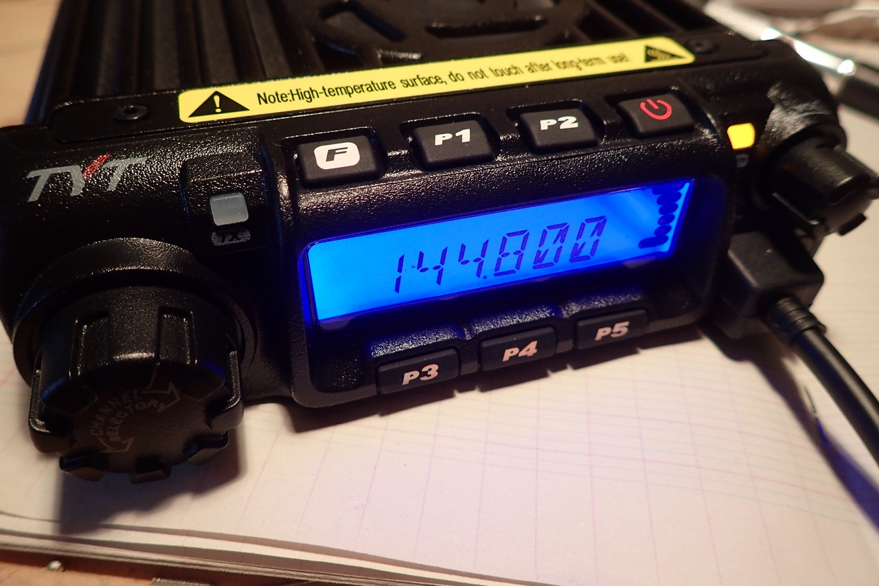
I was in the market for another radio for my mobile APRS operations. After reading various articles (here and here) about the ability to add a D-SUB9 connector with all relevant signals for that matter. I ordered one, and it was there a few days later. Before modding the radio I wanted to program the relevant memory channels and test run it and there came the disappointment.
I use a Tinytrak 4 for APRS. The Tinytrak 4 sports a digital carrier detect (abbreviated DCD) allowing to run the radio with squelch fully opened letting the Tynitrak 4 decide if the signal is a valid packet signal or not. DCD is very effective and helps drastically reduce collisions on the air.
As a matter of fact I wanted to run the TYT TH-9000D with squelch fully open but it seeems that the engineers at TYT have a strange conception of what fully opened squelch means. The radio produces loud clicks every time a signal ends. Those loud clicks are actually just the symptom of a, IMHO, more serious design flaw : setting the squelch to 0 does not actually open it. The clicks are then generated every time the CPU thinks it is ok to close the squelch. I do not care about the click actually, I just want to have a fully open squelch when setting it to zero !
Here a video to illustrate this :
I Googled for a schematic and found one for the 220MHz version. I had no other choice to assume that the squelch circuitry is the same between both version. To add insult to injury, my radios board is a newer revision than the one in the schematics.
Next step was to understand how the squelch actually works. Using my oscilloscope and the datasheets of the various ICs I found out the following :
- The intermediate frequency/discriminator IC U7 (TA31136FN) outputs a voltage on pin 14. This voltage depends on the SNR level of the signal just being received. The lower the voltage, the lower the SNR.
- This voltage goes through U6 and is shaped to be in range 0 to 5V. Special warning here : there is a typo in the schematic U6 is actually U9 !
- The voltage coming out of U9 is then fed through R131 right into the CPU. The voltage is constantly monitored and compared to a threshold defined by the squelch setting. Depending on the squelch setting the CPU triggers the Q4 transistor i.e. shorts the audio amplifiers input to ground or not. Q4 shorts the input of the audio amplifier to ground, those creating a polarization change at the inputs resulting in the loud clicks on squelch opening/closing.
- When receiving only the background noise, the voltage is approximately of 4.8V. As I said previously when a signal is received the voltage gets lower. When the signal drops the voltage makes a quick pulse up to 5 volts and then goes back to approx 4.8V. The quick pulse to 5V triggers the squelch logic in the CPU closes the squelch and reopens it right after.
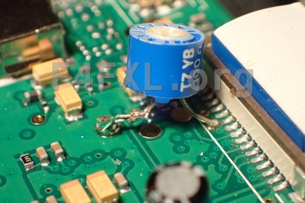
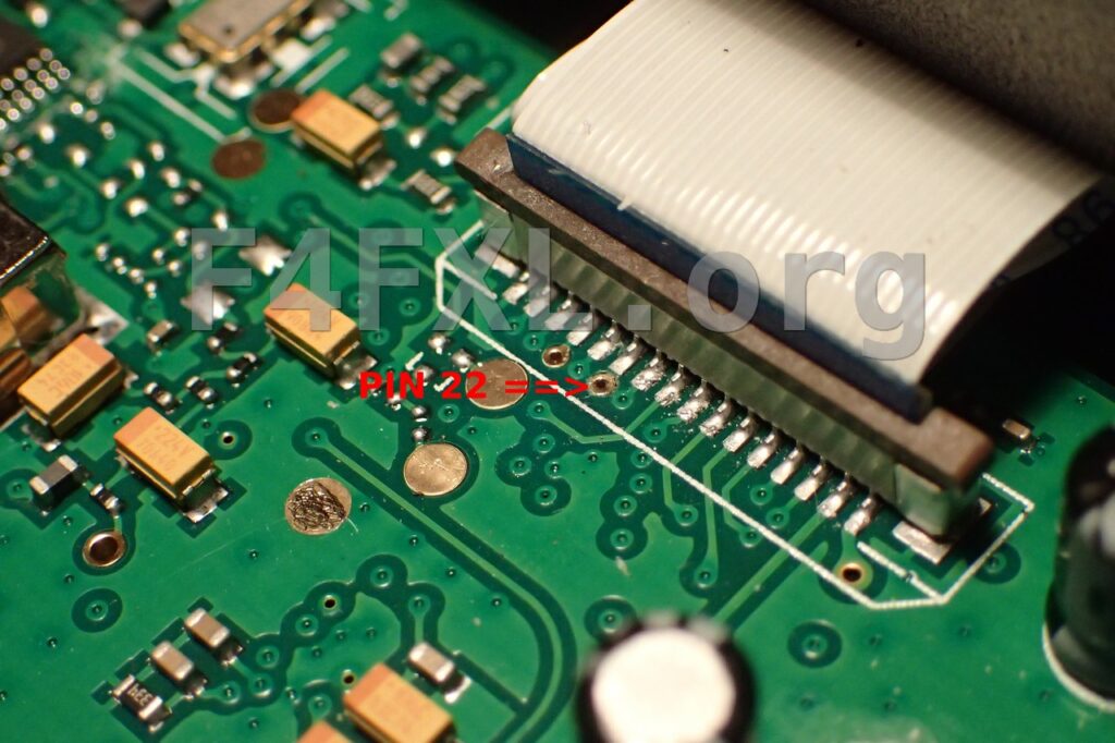
So far so good, we know how the squelch works. One of the options would be to change the values of the resistors around U9 hence changing its gain. U9 is on the opposite side of the main board. I am lazy and the idea of removing the main board did not look that pleasant. According to schematic the squelch signal goes to the CPU via the ZIF connector pin 22. Lucky me, it is accessible.
To lower the voltage the easiest way was to put a resistor from PIN 22 to ground. Since I was unsure what value to use I first started with parts I had in my scavenged parts box : a 100 Ohm trimmer. A few minutes later, the trimmer was in place and boom it works ! Now the squelch closes at approx a setting of 6, which is good for me as the radio will 90% of the time be used for APRS.
Next step, interface with the Tinytrak 4 !


You sir, are a hack. Pin 14 of U7 goes to an Op Amp, and the output of that Op amp (pin 7 of LM2904) goes to pin 22 of the ribbon cable. It doesn’t go to U6 or U9 or whatever, and has nothing at all to do with those (scrambler) chips.
Hi I’ve attempting to do this mod using a 100 ohm trimmer. Maybe I’m not understanding what the outcome should be. First mine is a 2m version. When I installed the pot I set it for 60ohms and in the software set the squelch to 6. After the radio was turned on and set for packet in my area. I could hear static. Any adjustment up or down of the pot would not stop the static even dropping to 1ohm. Adjusting the squelch to 20 in software was the only setting that pretty much stopped it. Should you be able to hear the static go away when making adjustment to the pot? My intent is to just the radio full time for packet so the static may not be a problem but I would think that making the adjustments you would be stopping the stactic
Hi James,
The radio is currently at our club local serving as an APRS digipeater. So I cannot answer your question (this projects dates back a couple of years now). AFAIR adjusting the pot changed the value at which the squelch was fully open, in my case squelch was open at level 6 and below.
However, the outcome I wanted is ti have a fully open squelch when setting the squelch to 0 in the software. I.e I wanted to have full static and not this “just above the noise” squelch setting the radio had when I got it.
Can you clarify, did you have the pot set to 100 Ohm, or something else?
Hi Ben,
The pot goes from 0 to 100Ohm I had it set to approx mid-way. Currently the radio is being used for a digipeater project I do not have it handy to check the actual value. When i installed the pot I did not measure the value though, just adjusted the pot until the setting the squelch to 0 had kept it open.
Yes … but, did it stop the pop??? The click … that annoying sound that drives me crazy?
Reid Snider
N4SPY
Hi Reid,
The pop sound is caused by a bad audio circuit design. What is done here makes sure the squelch is actually opened when set to 0.
Maybe adding a coupling capacitor somewhere in the audio circuitry might help.
73
Geoffrey
Very good project. Will be following. I am planning the same thing with the same radio.
KE8BDY
Hi, thanks for your comment.
In the mean time I finalized the project : https://www.f4fxl.org/aprs-with-tinytrak-4-and-tyt-th-9000d/
Pingback: APRS with Tinytrak 4 and TYT TH-9000D – F4FXL
Pingback: Solved TYT TH-9000D Gibberish Characters Issue – F4FXL